The 25th of February 2019 I started the build of a Mk-VII Paraset, the wooden case model and a power supply, also in a wooden case, like in this photograph:
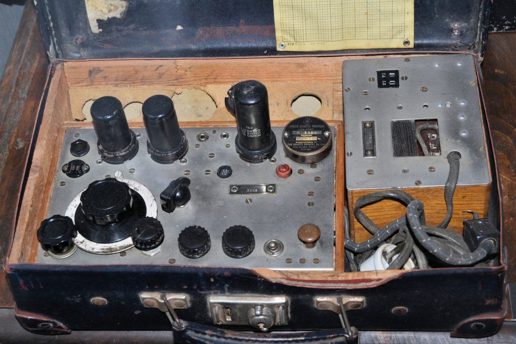
Gathering parts, in my case, is today not such a problem, as I can pick freely from the Paraset Warehouse. I agreed with Eric to make the outside of the Paraset looking more or less authentic, but use modern parts “under the hood”.
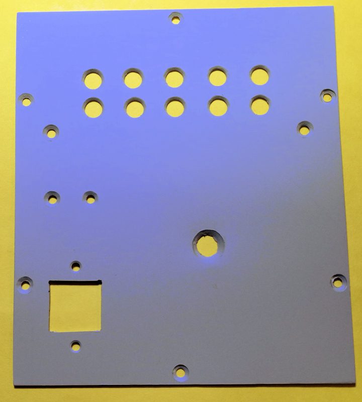
First thing to do was to countersink the water-jet cut holes in the factory made front panel:
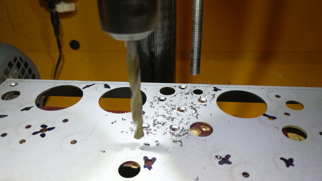
As you see, I clearly marked the holes that were NOT to be countersunk.
Next thing to do is to clear up the workbench in the garage, to make room for the spray-painting job. I will be preparing 3 front panels at the same time, to have a few painted panels on the shelf.
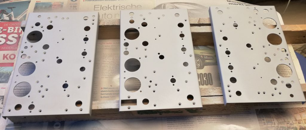
April 18, 2019. Finally! Temperature and moisture level in my garage are finally acceptable to spray paint the three panels I drilled earlier. They all got 3 coats of flat grey paint. I will leave them rest for a few days so the 2 component paint can harden.
Next thing to do is to put on the lettering. Or making the needed mechanical parts in the meantime. Phew! A lot to do, but great fun!
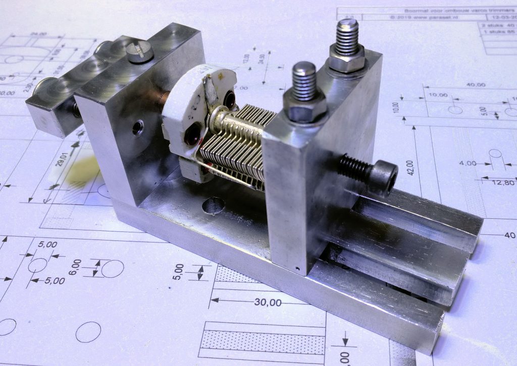
April 2, 2019. Some weeks ago I started the build of a new jig for modifying trimmer variable air capacitors into variable air capacitors with a shaft. The latter types are almost unable to find anymore. I had made a wooden jig before and that worked also, but had a few issues. So I made this:
To be able to see the adjusting of the vanes properly, I mounted an affordable digital microscope, that I can also use for other jobs that need magnification.
Next step is to take 3 varcaps apart and to cut off the extended bearing:
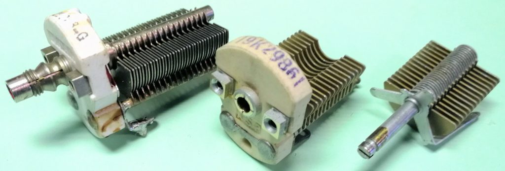
To the left, the original varcap without the blocking nut. In the middle the one with the cut off bearing. To the right the rotor and pressure spring.
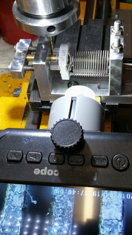
Than, the varcap and its new shaft go in the jig and the vanes are adjusted. Than a hole through and through is drilled to receive the blocking pin, a 1,2 mm brass nail that is riveted. Below, the varcap in the jig. On the bottom you see the image of the vanes on the microscope screen.
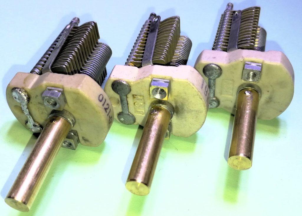
And finally, after a while, you end up with the 3 variable air capacitors:
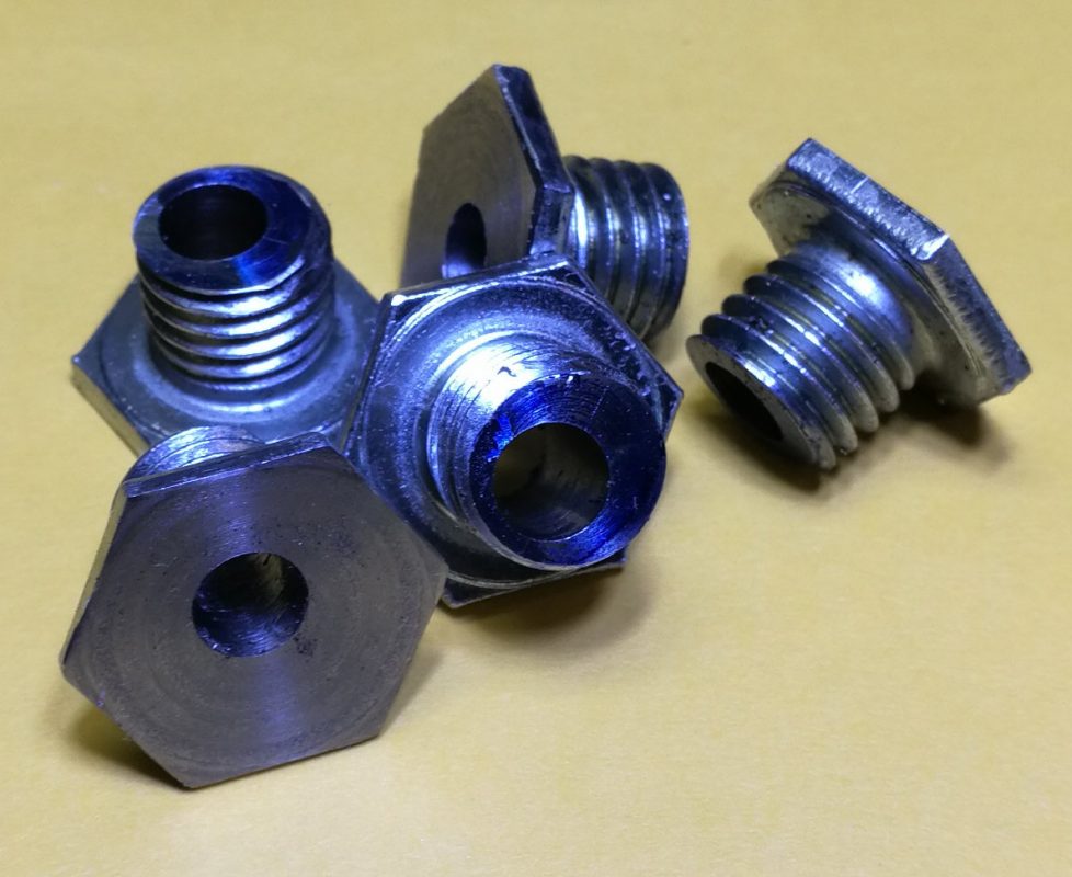
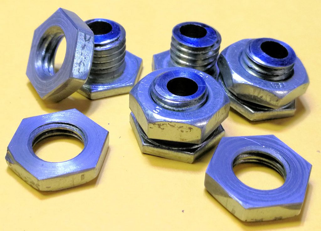
June 3, 2019. I have completed some more mechanical parts. From M12 bolts I made the bearing for the vernier drive. One starts with 5 of these:
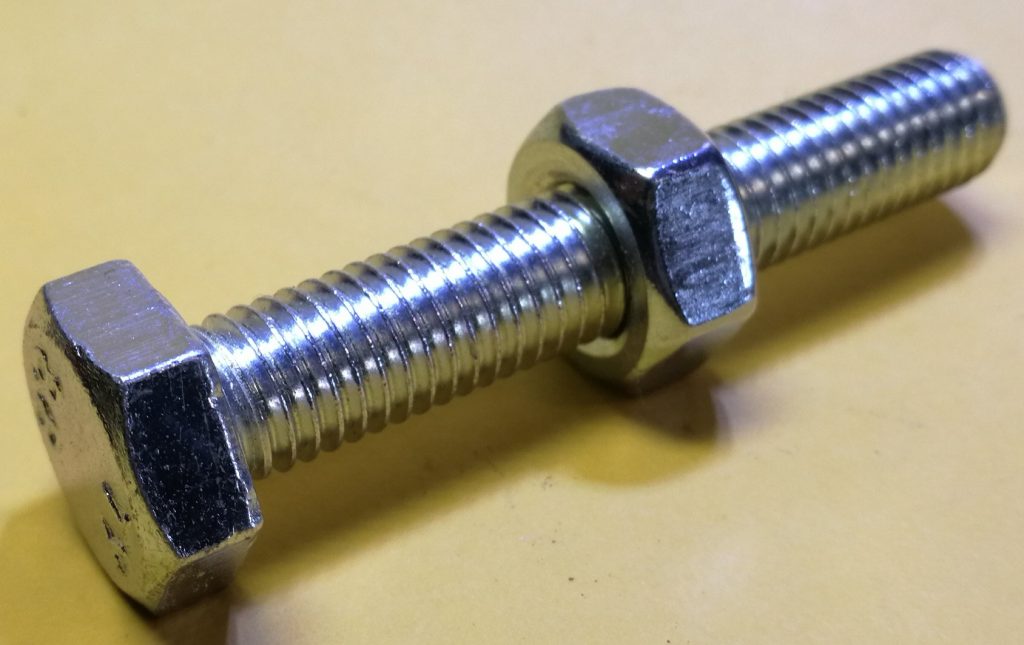
….. and after sawing, and turning, they become like these:
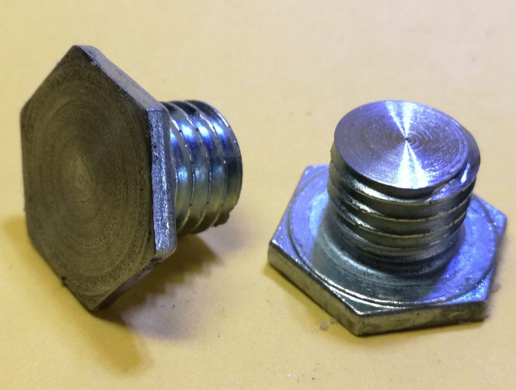
Than drilling the hole for the shaft. First I used a 3 mm drill bit:
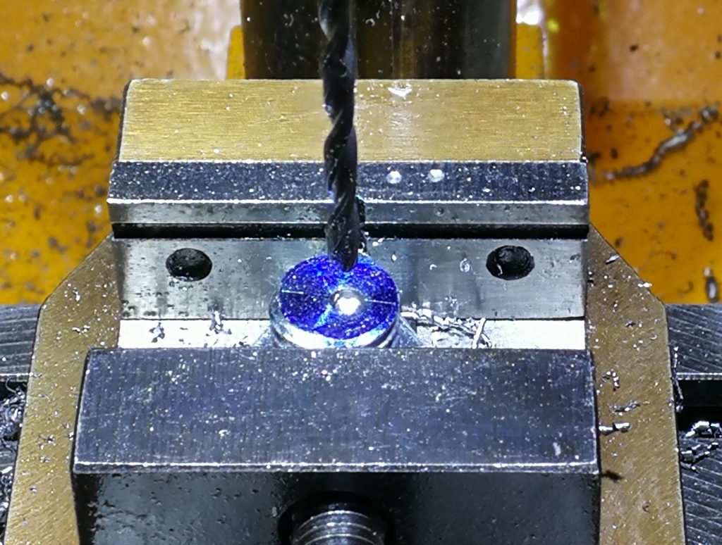
… and after that a 1/4 inch drill bit:
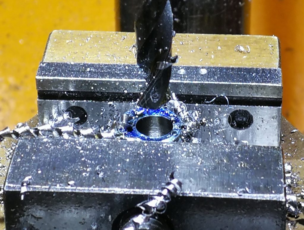
Resulting in 5 of these:
Now, that is only the bearing. Notice the hole is off centre. That is for adjusting the grip on the driver plate, under the dial. You will see that later.
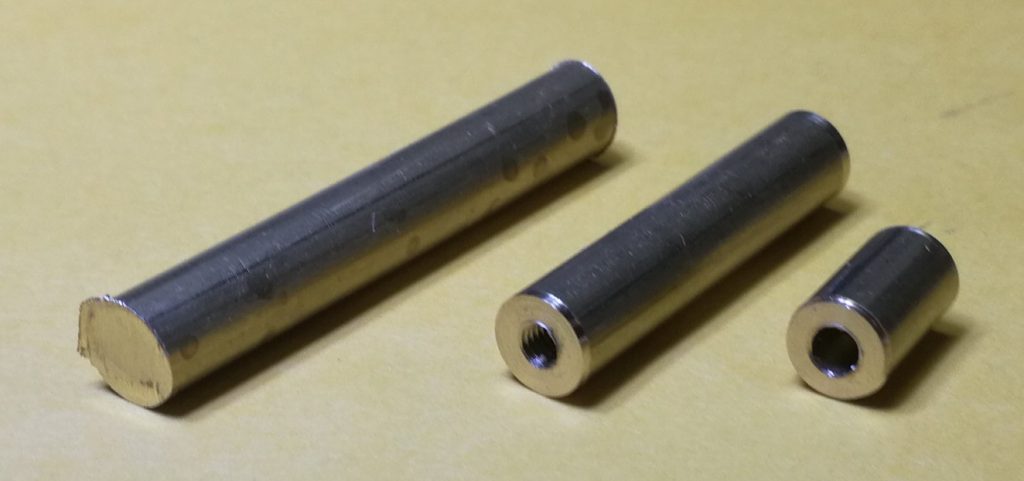
Next is to make a shaft. On the next photo you see a piece of 40 mm brass rod, 1/4 inch diameter. In the middle the tapped bottom piece, to the right the untapped top piece.
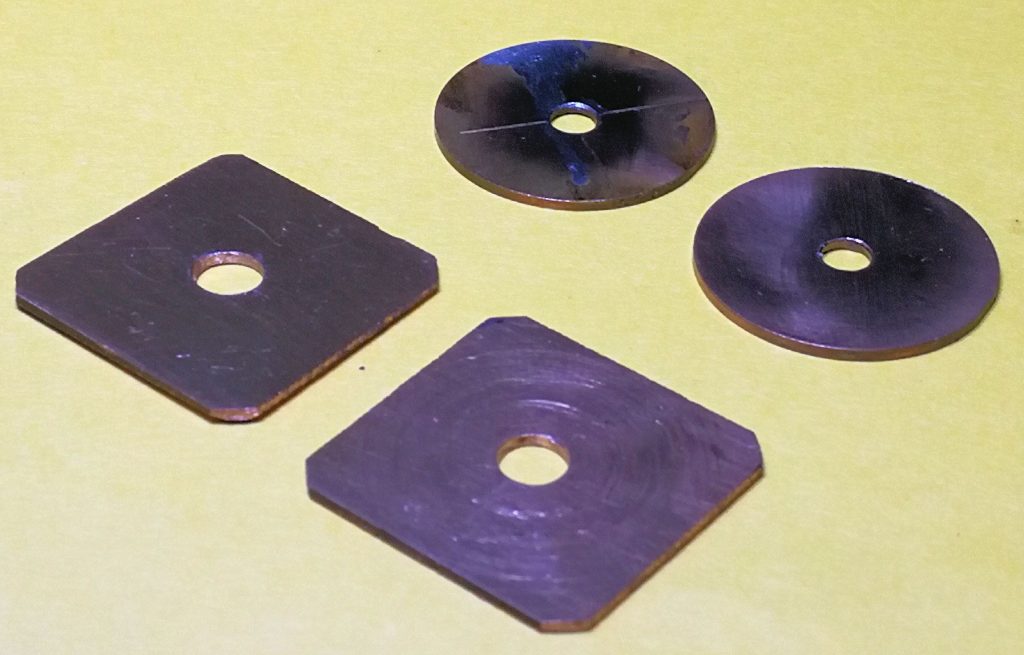
I cut out of a piece of brass sheet, little square pieces. Square because that is easier to cut than round. The sheet has to remain flat, so I used a hack saw to cut them out a sheet of brass. I made them round on the lathe.
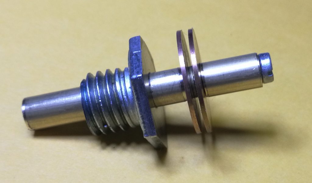
When you assemble these parts, you will end up with 5 of these:
Finally I decided to cut the nuts in half. As sawing would be a tedious job, I used the angle grinder to take away about the half of the nut’s thickness. A finish in the lathe to make them properly flat did the rest.
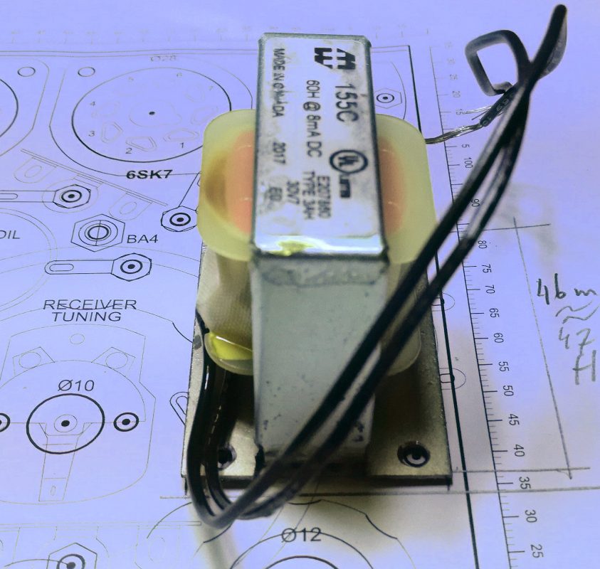
Next thing to do is to make a mounting sheet for the 60 mH rf-choke. The Paraset used a type of choke that had 4 mounting holes. The modern chokes we can get our hands on, have only 2 holes, and these don’t correspond with the holes in the front panel. The solution to this problem is to make a fitting mounting sheet on which the choke is mounted. Here it is:
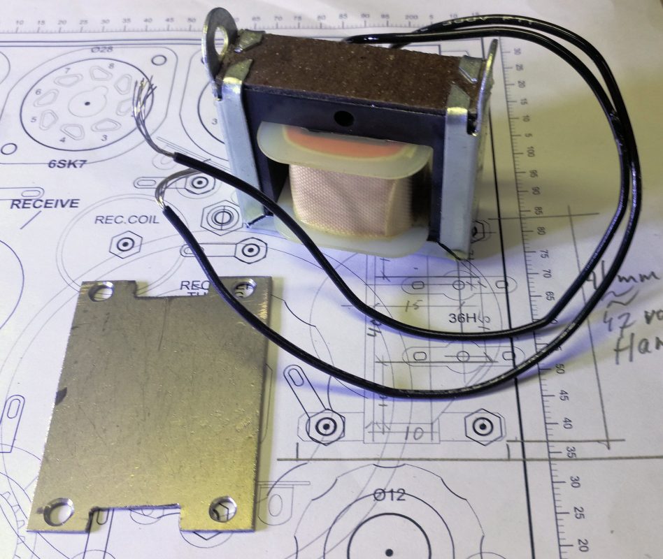
And here you see the parts put together:
June 7, 2019. Today I made the coils. I began with the raw formers and polished them. In the TX-coil I made groves to accommodate the 1 x windings for the light bulbs:
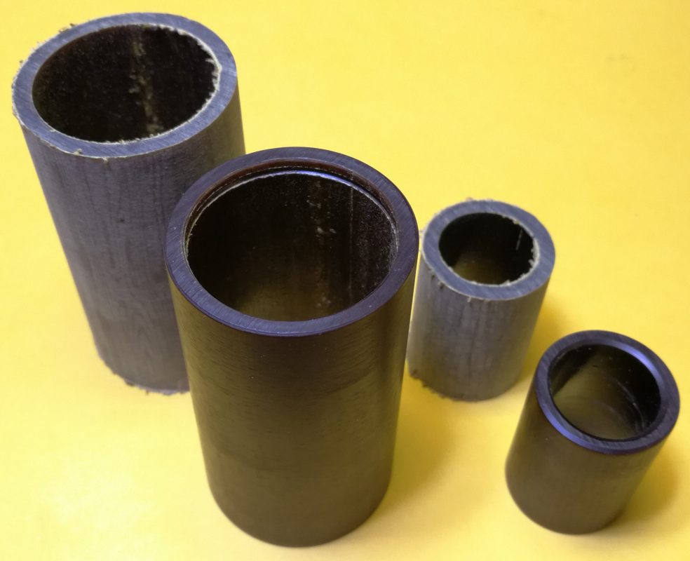
After that I put the windings on. Three sizes of wire are used. Last job is to cover the wires with varnish, to keep them in place and moisture out.
June 16, 2019. It is inevitable: the legend on the front panel is the next thing to do. After that, mounting of components can begin. So I laid yesterdays fake news on the table to work on, fetched a bowl of water and started cutting the text transfers. Now, you can’t draw pencil lines on the panel to align the text, it has to be done “at sight”. In the old days they used silk screen print, I guess.
The first three transfers I ruined. I had to get the hang of it, again. After those first three, it went all right and after a few hours I ended up with this:
Now I will let it dry over night and tomorrow I will put a few layers transparent varnish on the panel, to protect the transfers.
June 22, 2019. Time to mount the necessary hardware, like sockets and solder lugs and alike. I’ll have to wait before mounting the variable air capacitors, I have to find suitable knobs before knowing the length the shafts have to be cut.
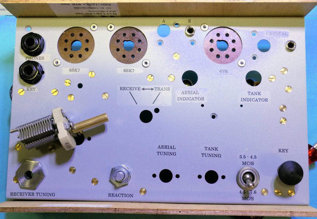
July 13, 2019. Last few days I have been busy filling up the front panel with the last mechanical parts. Also soldered in some components and wiring. It is certainly going somewhere! The big empty space is where the TX coil will be fitted. The Rx coil is already in it’s place.
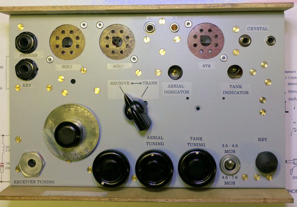
Let’s flip it around. The scale is a temporary one. It will be replaced by an original, later. The other knobs are at least 60 years old, from war production tuning boxes for the BC610 transmitter.
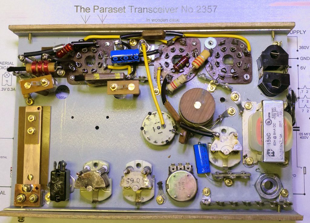
August 05, 2019. The past few days I worked again on Eric’s Paraset. All parts are placed, almost all wire connections are laid. Not long before the smoke test…..

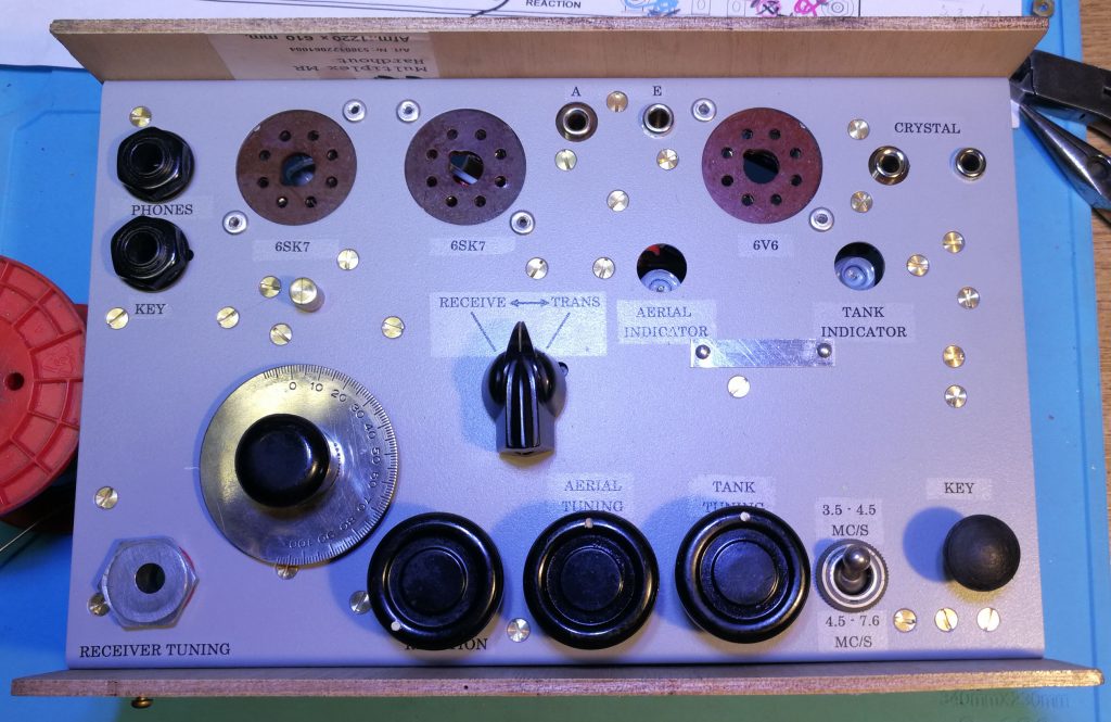
On the front some things have changed: the index for the dial and the serial number plate. Unfortunately I don’t have number punches, small enough to fit the serial number plate. I tried engraving by hand, with a milling bit in the Dremel Moto-tool, but that looked horrible. So I will leave it blank for now.
September 1, 2019. Today made the last connections in Eric’s Paraset. Fitted temporary power cables as well. These will be replaced by a textile covered cable, once the wooden cabinet is ready.
Now smoke testing. Checked voltages without tubes: looking good.
Tomorrow fitting tubes and check again. Where is that transformer I ordered for the PSU?
2019, September 2. The transformer came in. No opportunity to continue on the project.
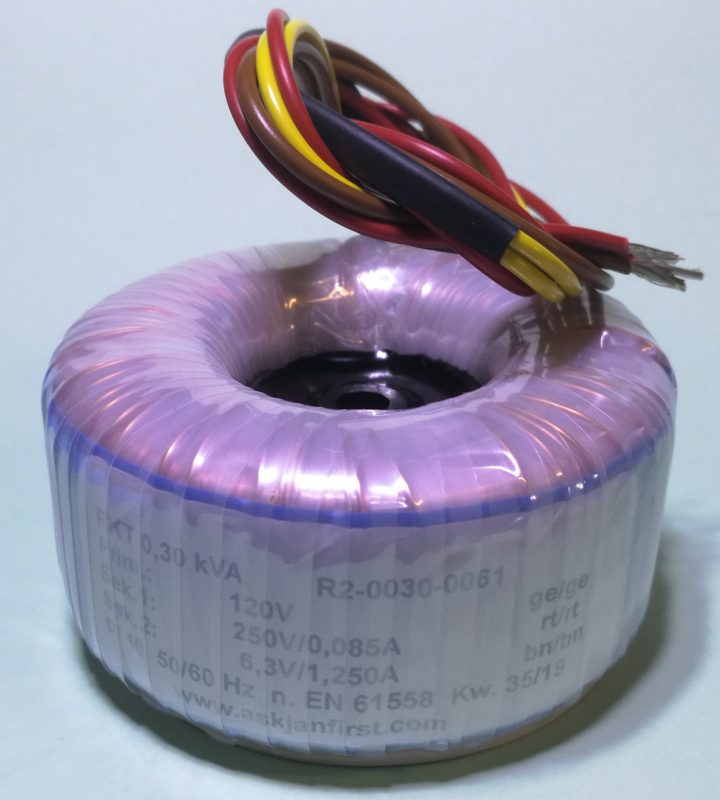
November 14, 2019. After a long period of other chores I finally got time again to spend on Eric’s Paraset. As the transformer had arrived, and I felt it to be best to tweak the Paraset on it’s own PSU, I decided to get a go on that.
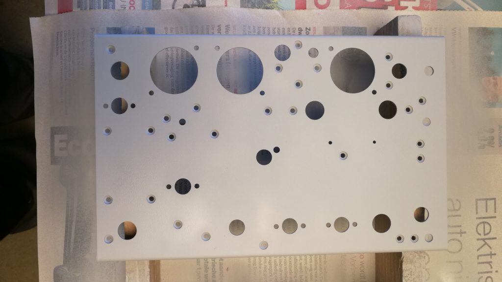
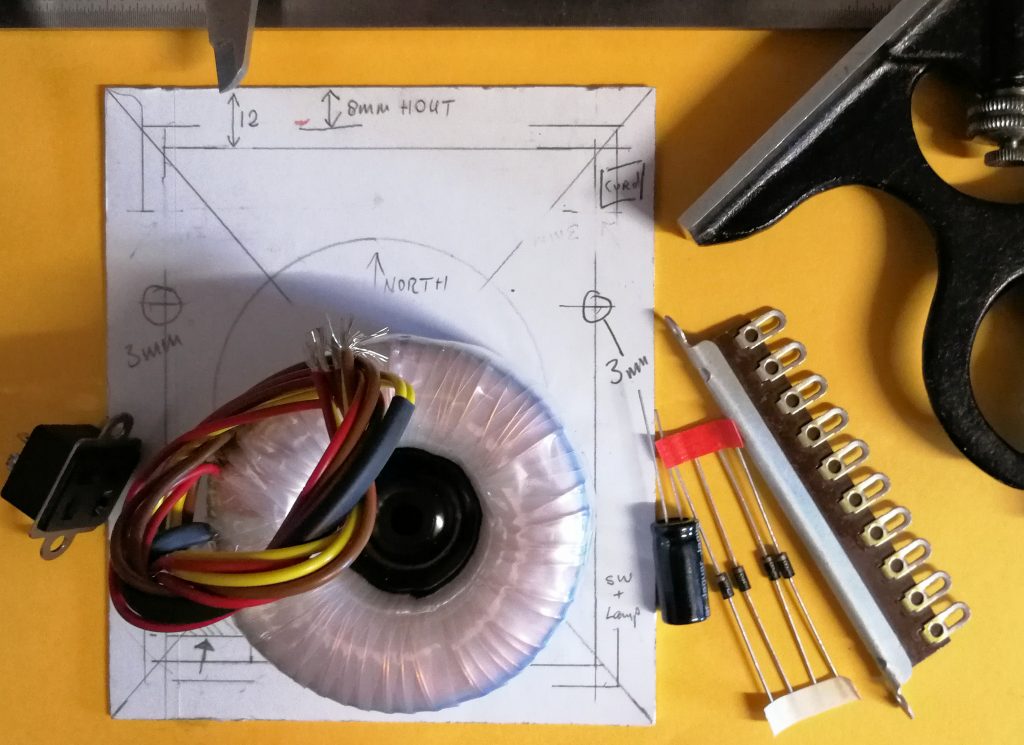
I cut a panel and made a drawing on it how to organise the parts. As we don’t have drawings of the wooden box power supply and I was going to use modern parts, I had to improvise.
Look at the photo on the top of this page and you will see differences. For safety reasons, I don’t like the rectangular opening showing the wires of the transformer. You don’t want anyone to poke around with their fingers in there. I also don’t like the power cord coming out of the top panel, because it will certainly break, in time. Let’s drill holes and spray paint the panel, first……
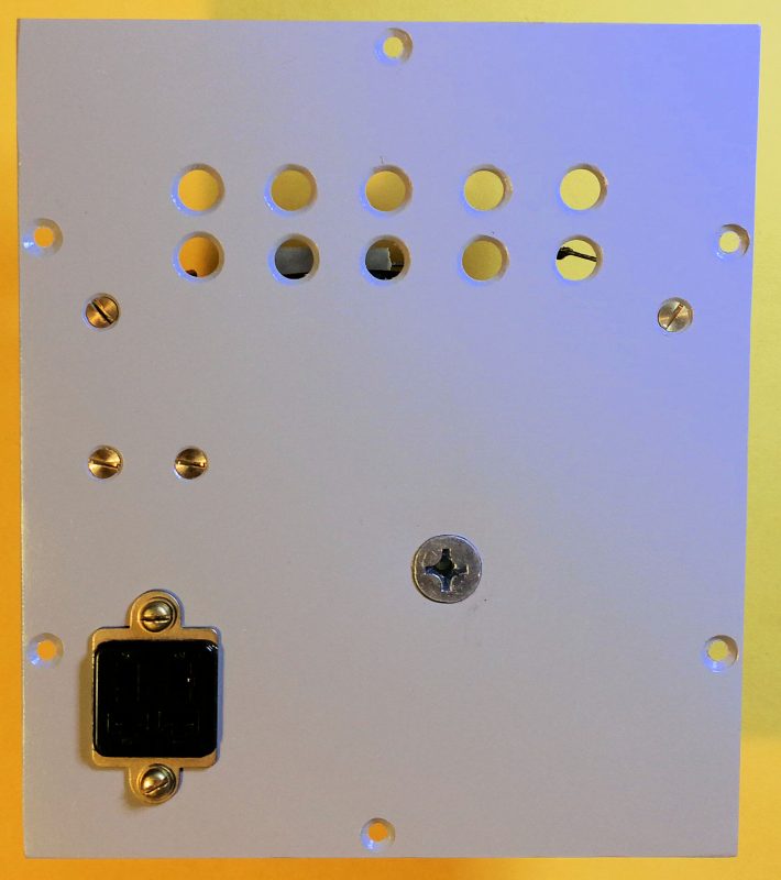
Well, that looks good. A couple of layers of that same flat grey epoxy undercoating I used for the Paraset panel. And a few layers of flat varnish because I did that on the Paraset panel as well. Let’s mount stuff!
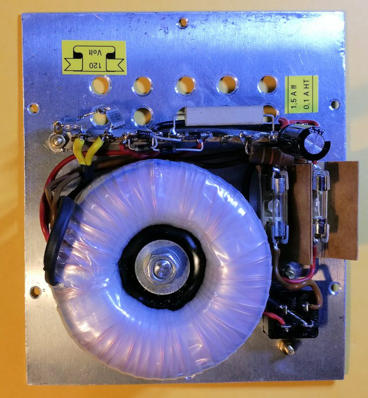
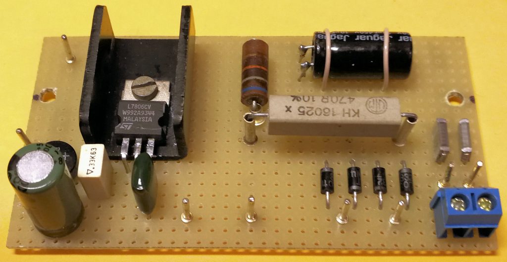
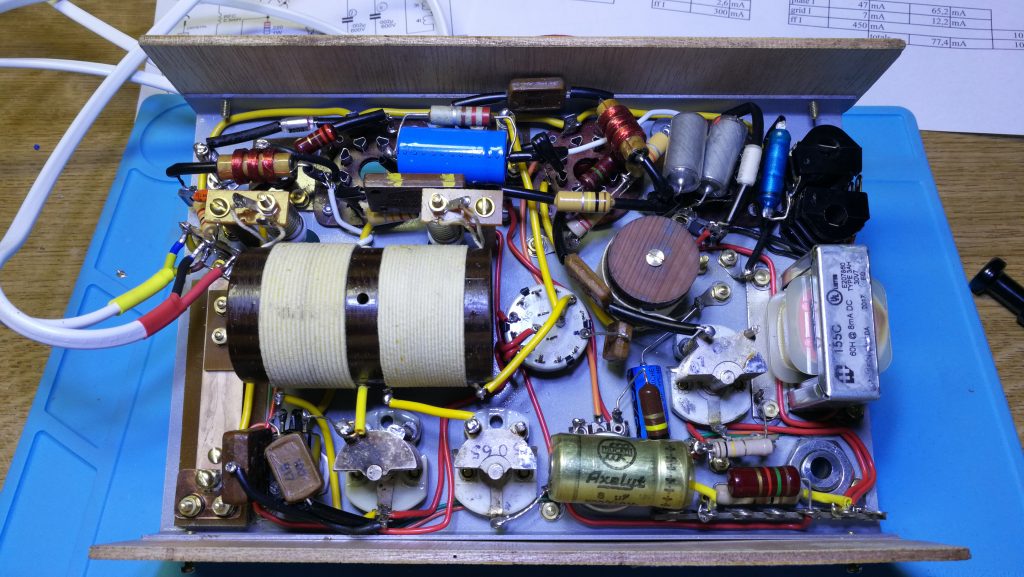
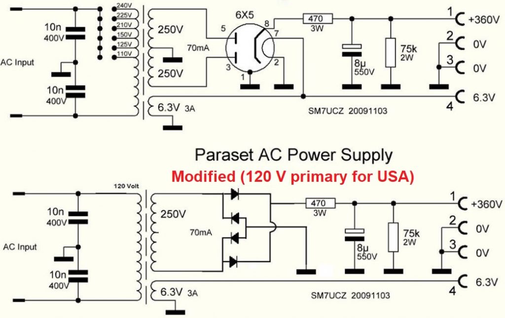
It is a very simple PSU. I did not use a tube, but made a FULL-BRIDGE-RECTIFIER out of 4 diodes. And this is how it looks top side. The color on the photo is a bit distorted because of the mix of lights shining on it during the take. The color is however, flat grey.
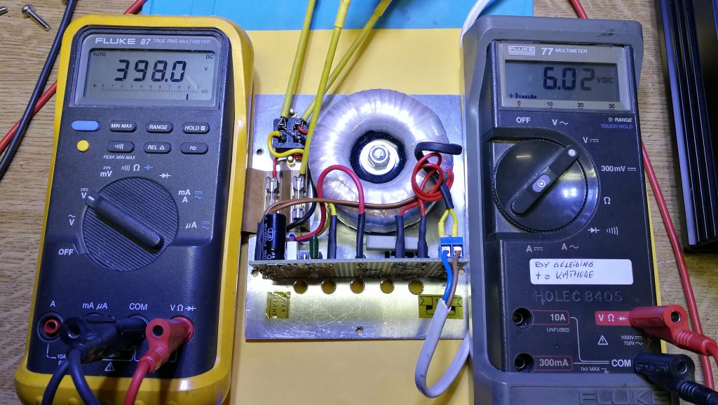
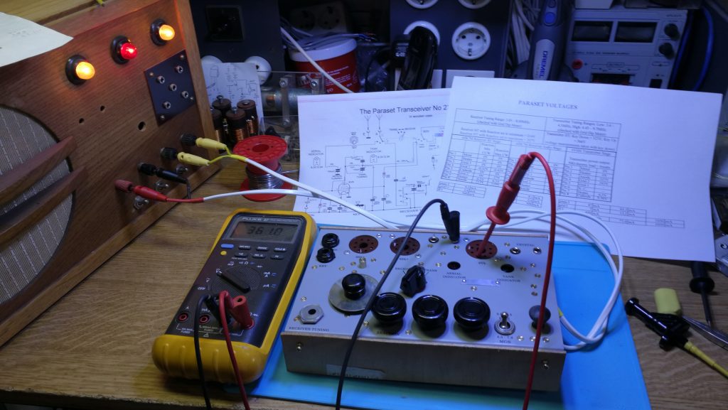
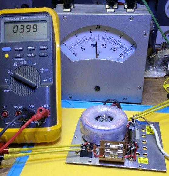
Time for the smoke test. No smoke seen. Left meter shows DC output voltage, right meter shows AC input voltage.
The original and the modified circuit:
Next is to build the power cable for the set and than hook it up and do some measuring.
November 19, 2019. After measuring voltages under load, it appeared that the filament voltage was 7,32 Volt, when the primary AC voltage was set to exactly 120 Volt. That is too high.
When the Paraset was powered from a lead-acid battery, the voltage would be 6 Volt.
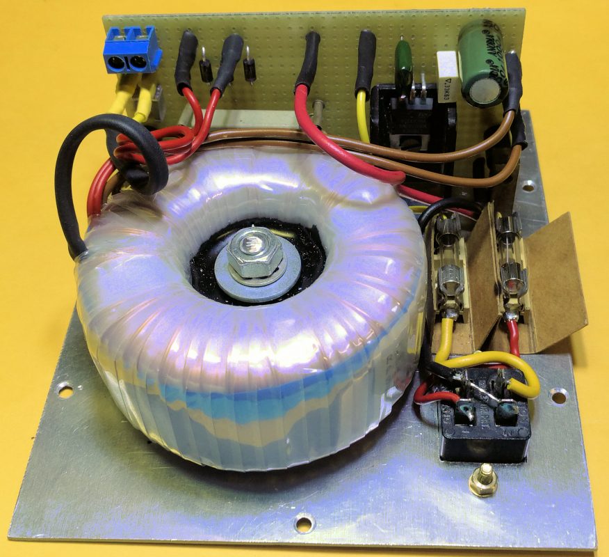
So I decided to rectify the filament voltage and lead it through a 7806 stabilizer. Unfortunately there was no room for the necessary parts on the existing mounting strut. So I decided to remove that and put all parts on a piece of Vero-alike board. On all wires coming from the transformer connectors were soldered to make the board flexible and detachable.