The
Paraset Breadboard Mk-I
(or probably called in 60
years: The Velp MK-I)
|
| Some
photo's can be enlarged: watch for the little hand! |
last update:
2010-03-08 |
|
|
|
|
|
Home |
Comments and/or
questions? Do you want to be notified if there are changes on this page?
Mail to: henk AT vanzwamcs.com |
|
|
|
The production of my Paraset stagnated because of lack of the right old
parts. As I could not wait to go on, I decided to build something so I
could experiment with the Paraset schematics. It had to be a kind of
breadboard, but rather universal, so it could be used for other set ups
as well. During the process I discovered that some things could have
been made different with a better result, that is why I named this set
up a MK-I. The next one will be more universal and more versatile.
I decided to use a kind of printed circuit board as a base. But as I had
not made a PCB for many years and I had no more chemicals to do so, I
decided to use a technique that a good friend, Stef PA0PSI, had shown
me, many years ago.
|
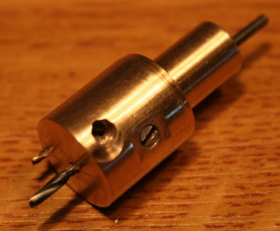 |
Stef showed me a little tool he used to make little insulated islands on
the copper side of a non-etched piece of PCB.
So I made the tool. It is a holder for a small centred drill bit and
a small drill bit off- centre, that mills the island, so to speak.
To give you an idea how to make the tool, I made a drawing, that can
be downloaded by following
this link.
The measures in the drawing are just a guidance. Feel free to alter
these. |
|
|
|
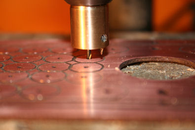 |
Next thing to do, was to mill the islands on the copper side of the PCB.
So I cut off a strip of a large PCB and made the three holes for the
octal sockets. I didn't make a proper plan but improvised carrying out
this project. So things did not fit as well as I hoped for. Well, it
will be better in MK-II. |
|
|
|
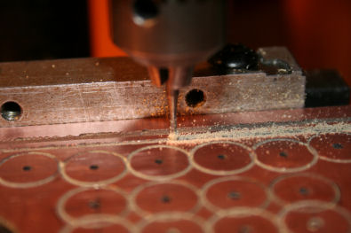 |
I also milled "rails" for B+, earth and filament current. This was done
quite easy by sliding the PCB along a guidance bar. |
|
|
|
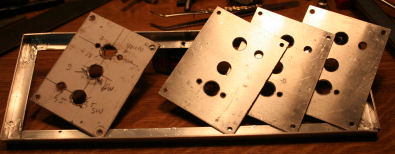 |
Than a way to hook up the controls had to be figured out. I decided to
make a number of small, universal panels that could accommodate various
controls. If later on different mounting holes for a certain control item
are needed, the simple exchange of a panel will do, the rest of the
panel(s) can be left alone. I made 4 panels of equal size, bolted them
together and drilled the holes in 1 action, through 4 layers of
aluminium.
The whole of panels is mounted in a rectangle, made of aluminium
angled profile. Because of the bad quality of the aluminium, that broke
on bending, I had to solder the joints. Yes, one can solder aluminium,
with a blow torch on 300 degrees, using a special soldering alloy. |
|
|
|
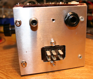 |
In order to make the contraption a bit sturdy, I added a side panel,
holding a Jones power plug, an RCA plug for LF out, and a jack for
phones. The small hole in the centre was intended for a 3,5 mm mini
jack, but that became obsolete. |
|
|
|
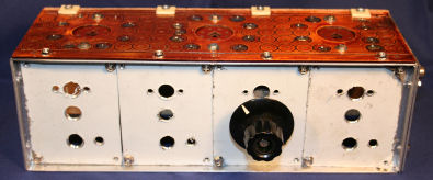 |
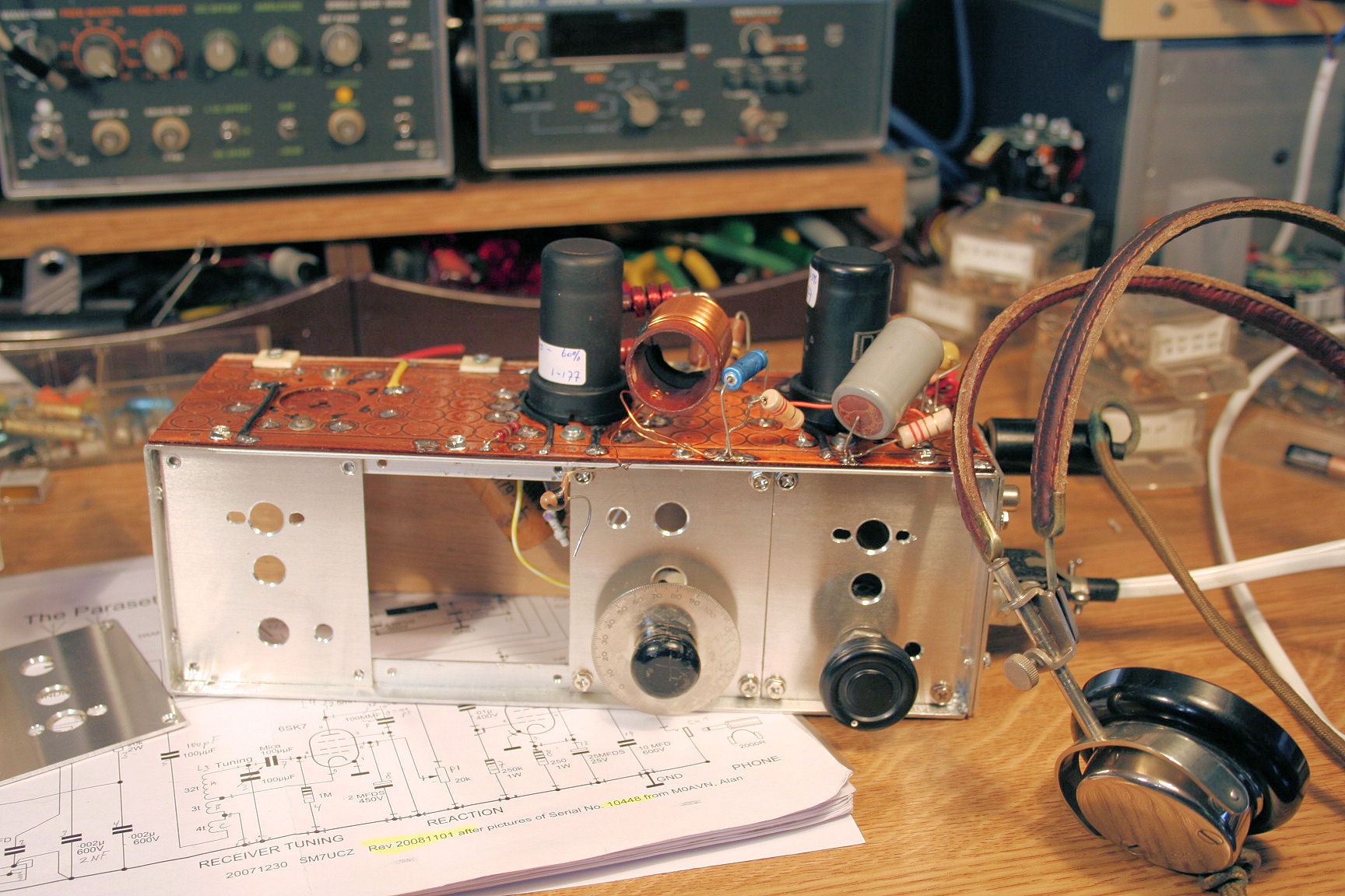
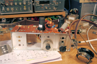
This is how it looks, assembled. There is still white plastic cover on
the panels. The back plane is made of plywood. In the MK-II, the PCB
will also be cut in modules, so modules using different tube sockets can
be combined. Even pre-fab modules can be combined. |
|
|
|
 |
After a few hours of searching components and soldering, it looks like
this. It is an ideal platform to try out components and substitutes
before putting them to the final Paraset. Soldering on the islands is
easy, changes can be easily made, measuring is easy. Everybody should
have such a contraption! |
|
|
|
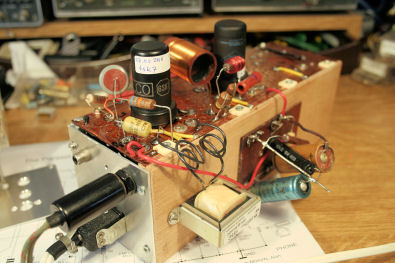 |
And the back side. Power supply and lf-chokes. The back panel is
plywood, so you can screw on to that what is needed. |
|
|
|
 |
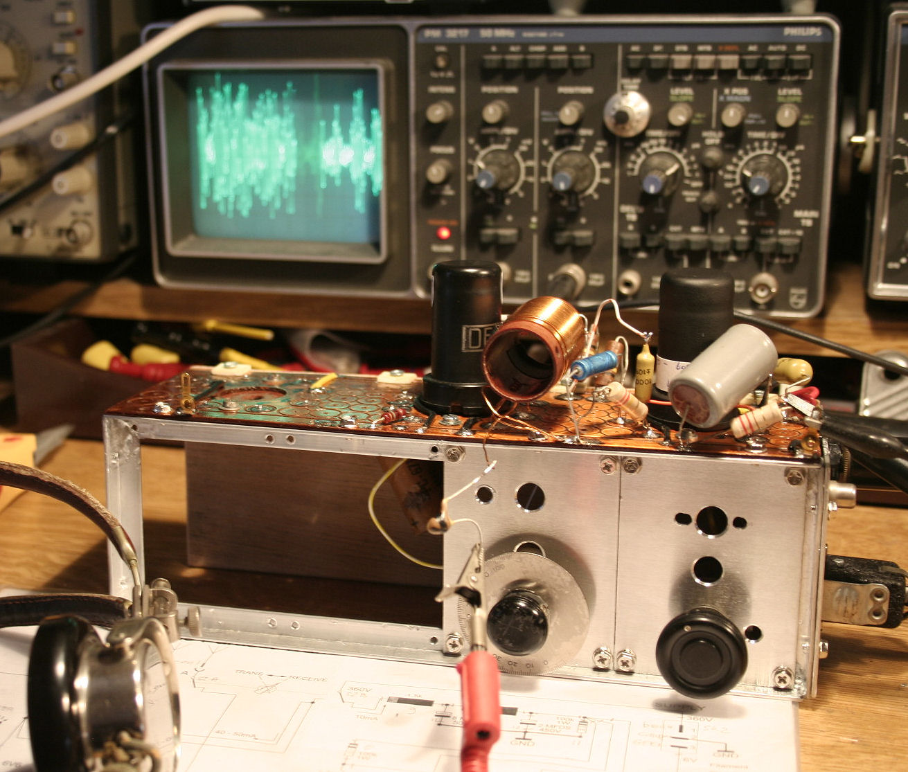
And than the RX-part is put to the test. A hell of a lot of noise came
out the headphones! The Germans must have picked up that noise on a mile
distance! I can't let you hear it, but the modulation on the scope
will tell you enough.
The frequency counter showed a tuning range from 3,053 MHz to 7,684
MHz. In the upper part were many AM radio stations to enjoy.
This gives a good feeling and one gets encouraged to go on. |
|
|
|
|
|
|
|
The MK-II will have wider pcb-panels. It will be the same size as the
front panels an contain one tube socket, each. |
|
|
|