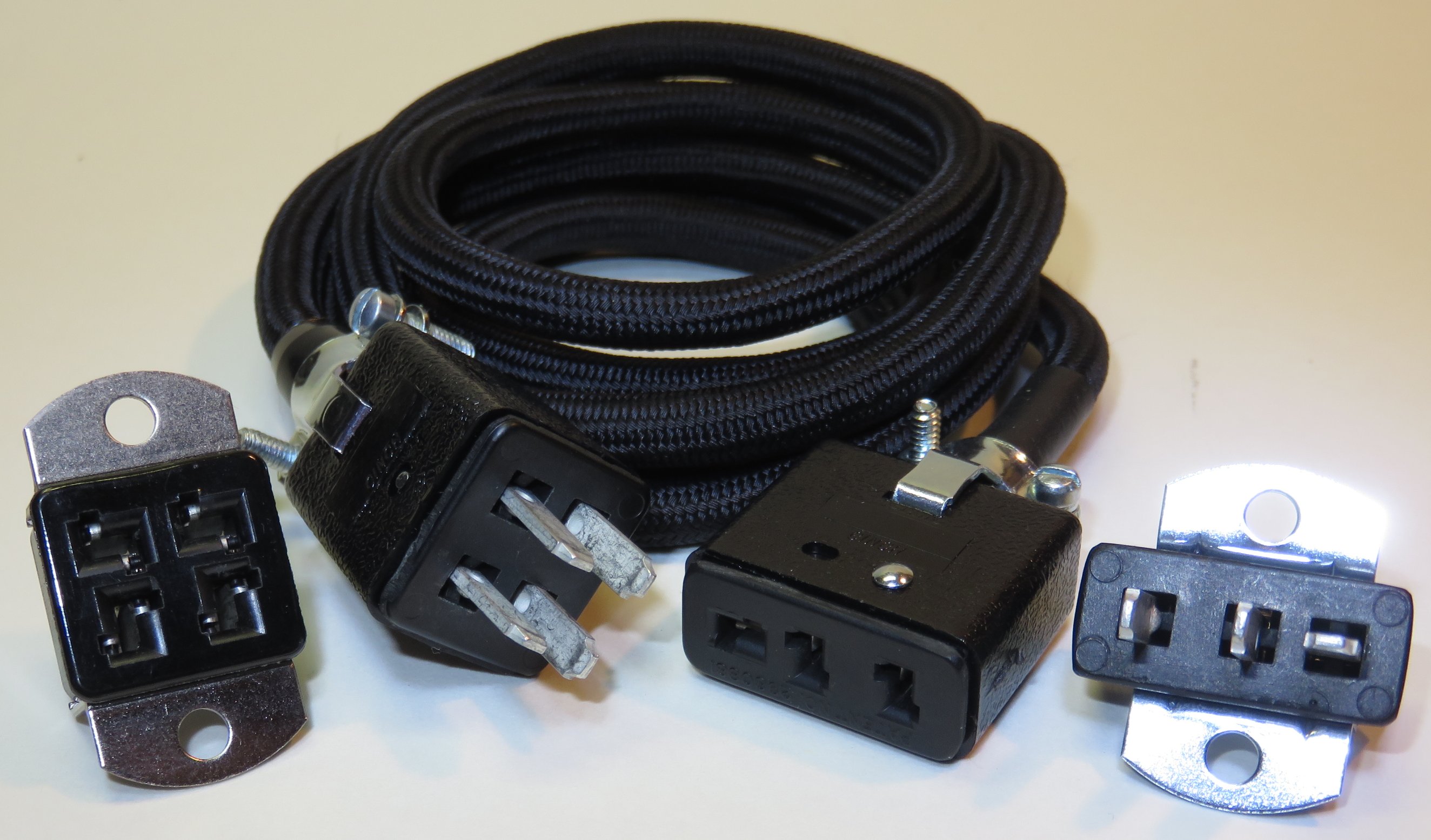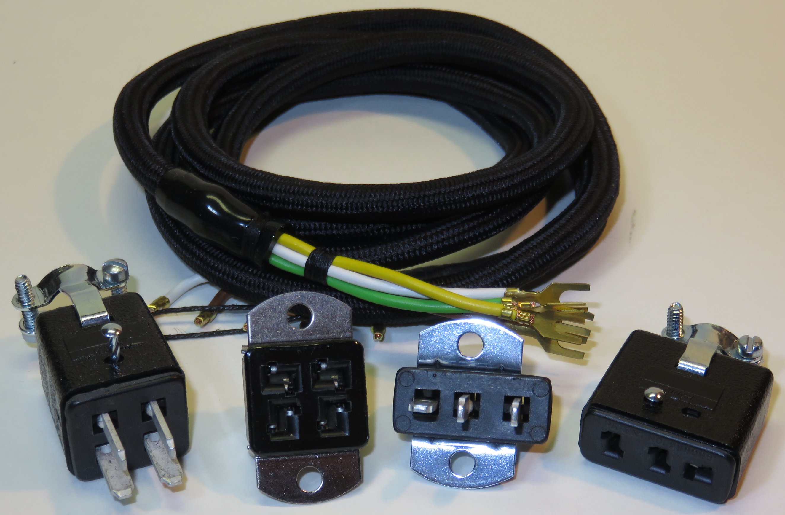
- Plug, 4 pins male;
- Socket, chassis, 4 pins female;
- Socket, chassis, 3 pins male;
- Plug, 3 pins female;
- Cable 1,20 m, smooth textile covered, 5 strains of litze wire 0,35 mm;
- 10 ferrules, 1 mm2 (not on the photo)
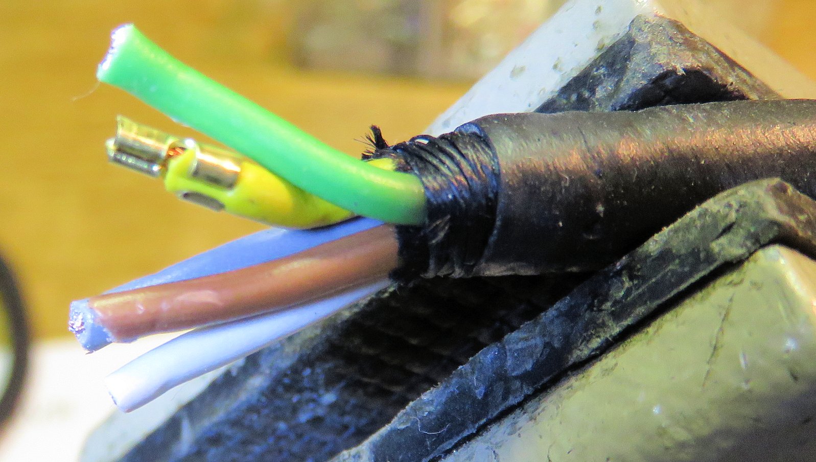
Slide the cap over the cable, cut the wires to length.
The yellow wire has the proper length, cut the others to the same length.
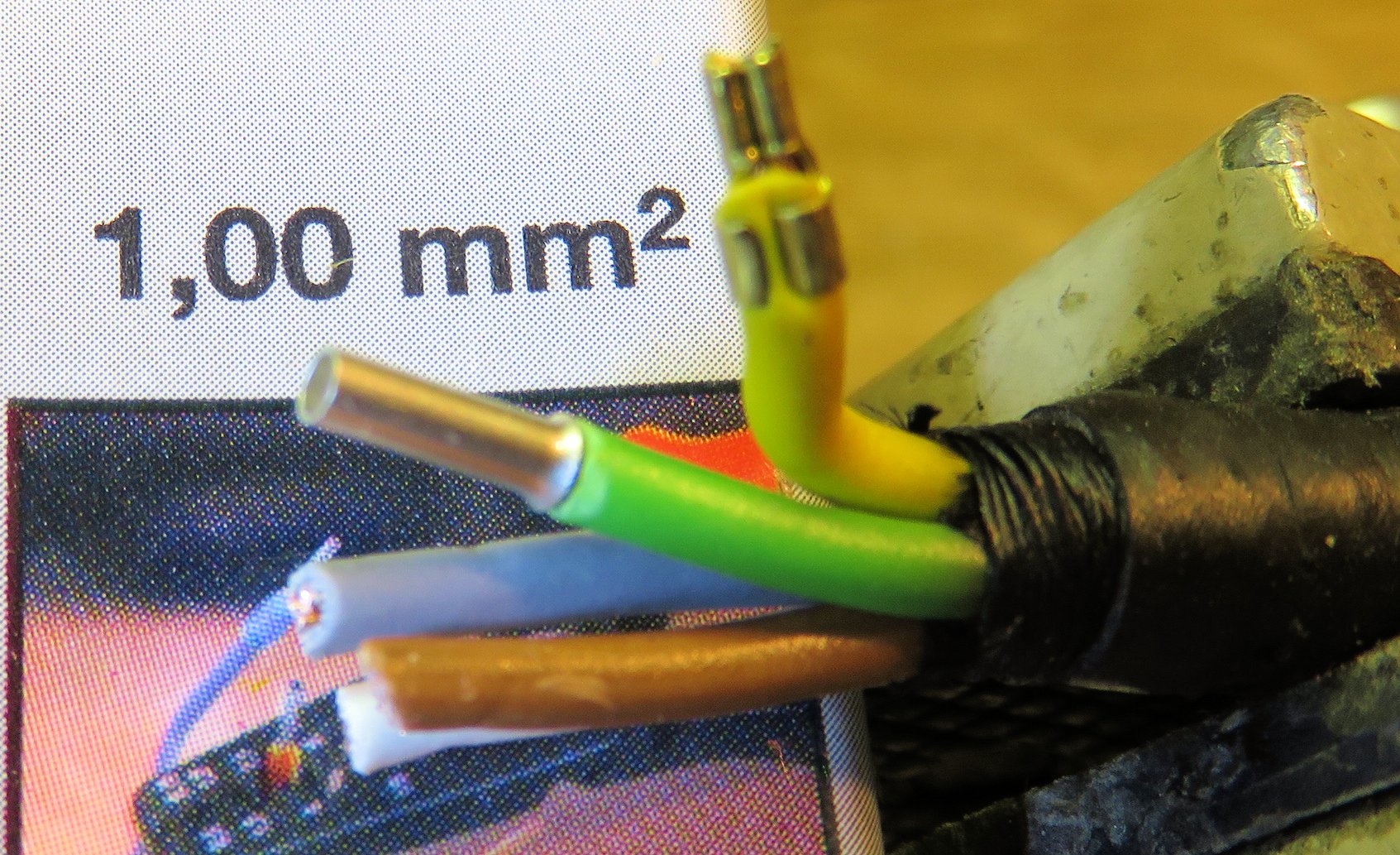
If you don't have ferrules, you can twist a length of thin solid wire around the litze and solder this.
Litze wire is difficult to solder without ferrule or a wire winding around it.
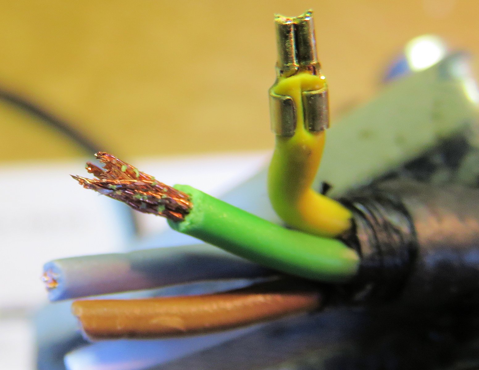
You need a pair of crimping pliers to crimp the ferrules, but a pair of combination pliers can do the trick as well.
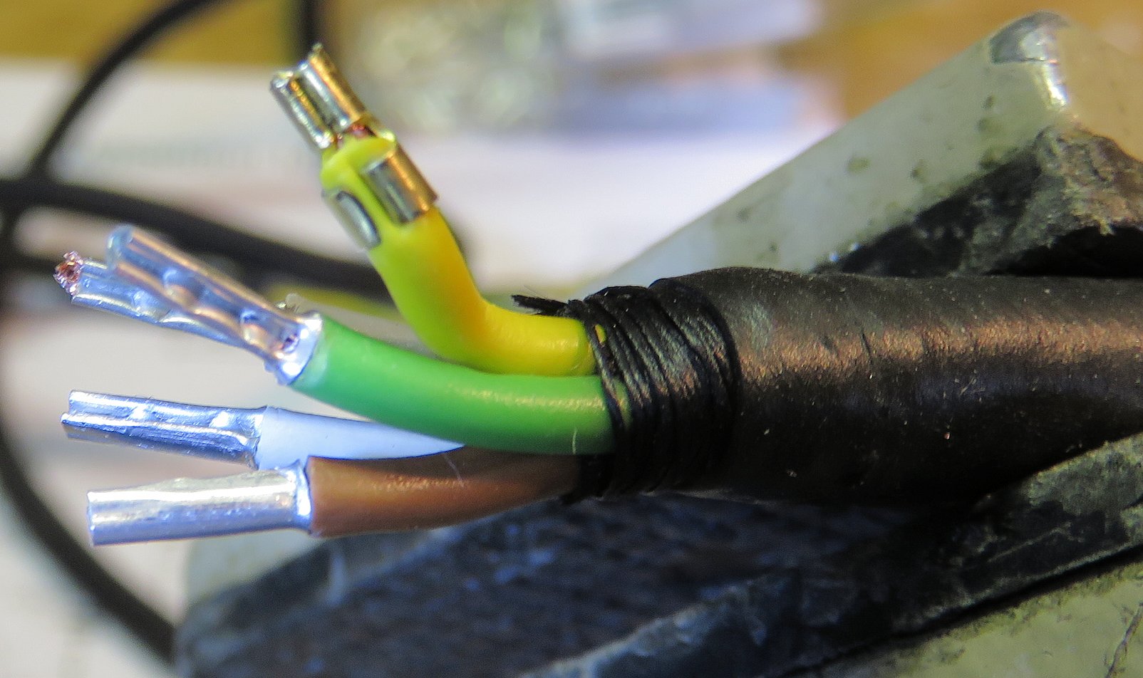
Of course you can decide to put a ferrule on the yellow wire as well, but it is difficult to get the copper end off, and the yellow cable is too short already to cut the copper end off and fit a ferrule.
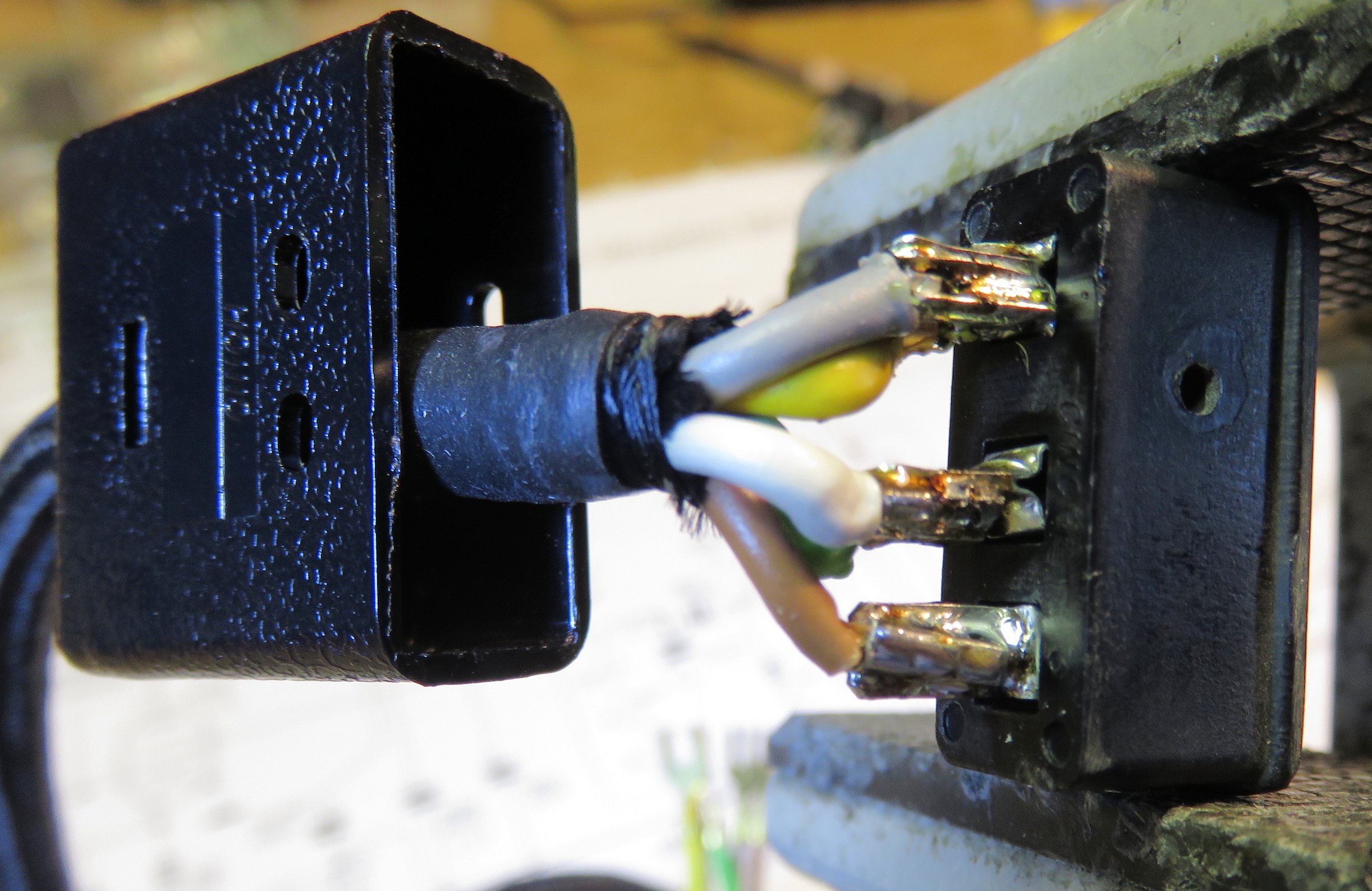
There are 5 wires for 3 pins, so we can combine wires or cut 2 off.
I used brown for HT, white and green for Ground, yellow and grey for filament.
The pins are all numbered, the schematic follows these numbers.
Finally we can slide the cap over the socket, stick in the special nail and mount the strain relief. This one is ready.
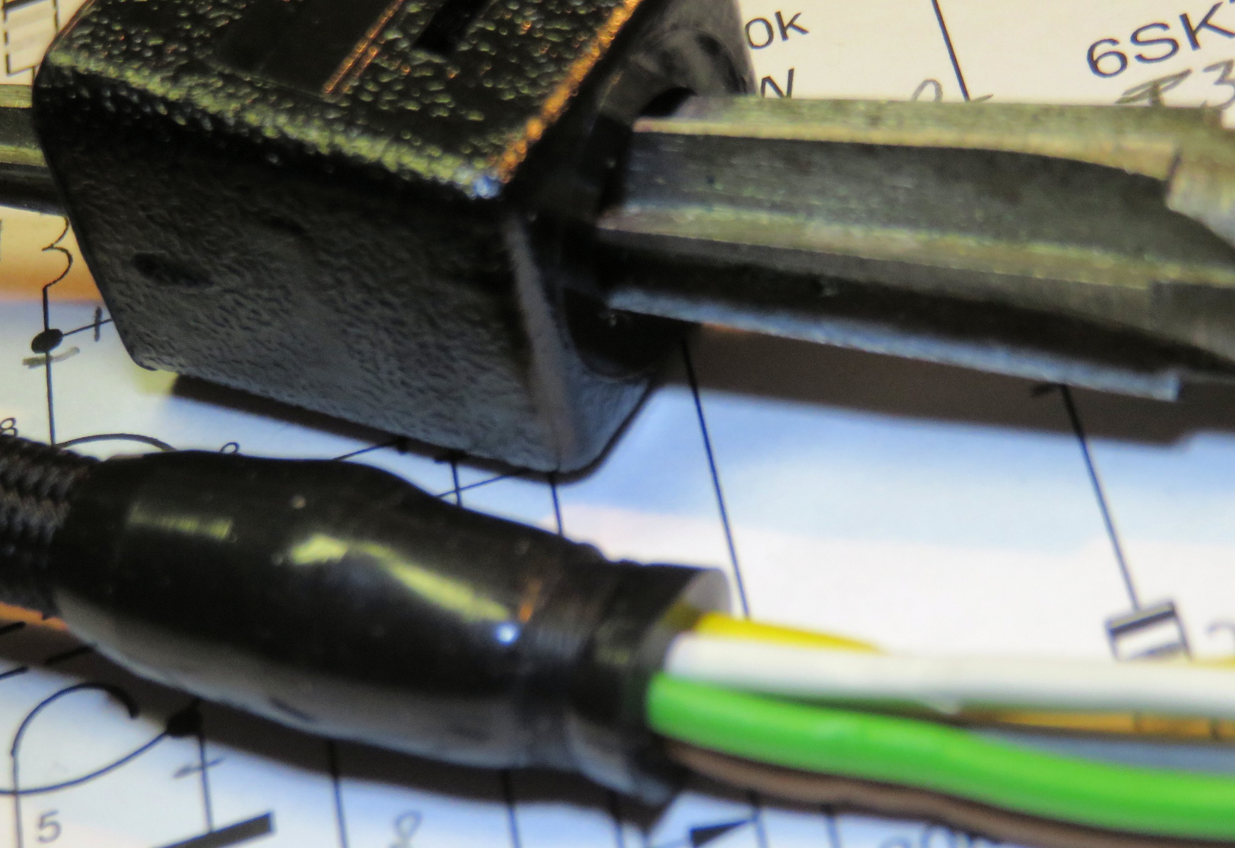
Next, slide the cap on the cable!!
Cut the wires to the desired length.
Strip the wires one at a time and put the ferrules on.

The pins are all numbered, the schematic follows these numbers.
Finally we can slide the cap over the socket, stick in the special nail and mount the strain relief. This cable is ready.